I. Key Link Easily Overlooked
Generally speaking, the R&D process of an inventor includes the following steps: (1) discovering and raising a problem; (2) determining a goal; (3) proposing a solution, e.g., new concept, idea, technology, theory, etc.; (4) conducting novelty retrieval; (5) confirming the solution if no identical solution is retrieved; (6) testing and verifying through experiments; and (7) achievements transformation.
The inventive concept employed throughout the R&D process, which is the process of framing an invention by generalizing the technical improvement made by the inventor in view of the background art, the technical defect of the background art, the technical means for overcoming the technical defect and the finally achieved technical effect, is concluded to form the patent application document.
During the R&D process, usually it is more difficult to propose a subject than to solve one. Hence, discovering and raising a problem is of great importance in the R&D process. Correspondingly, the process of discovering and raising a problem described in the patent application should be a key link of transition in the inventive concept. Here, the problem should be comprehended at least from the following aspects: firstly, the problem includes the universal technical problem know to those skilled in the art; secondly, the problem includes a new technical problem arising from the prior art; thirdly, the problem also includes the hidden causes for the technical problems of the former two aspects.
However, in the cases I handled, I noted that, when confronted with abstract patent application documents, correctly understanding the inventive concept, sticking to the technical problem in the inventive concept in particular, has always been a key link easily overlooked in the determination of inventiveness for patent granting, because the third aspect of the technical problem can be easily confused and directly be determined as the universal technical problem of the first aspect, resulting in severely underestimated inventiveness of the patent application.
Exemplary cases of this kind are analyzed below in reverse directions from the perspectives of the inventor and the examiner, respectively. From the perspective of the inventor, the inventive concept is traced to restore the process of R&D and formation of the invention, accentuating the crucial links of creation. From the perspective of the examiner, the inventive concept is assessed in the view of those skilled in the art. Particularly, it is assessed whether or not the hidden causes for the technical problems of the former two aspects is obvious to those skilled in the art prior to the application date. By the assessment from the two perspectives, the determination of inventiveness can be free from the influence of subjective factors. Hence, a preferable method of making a response is concluded to help the applicant obtain objective and fair assessment of the patent application and gain a reasonable scope of protection.
II. Typical Examples
1. Case 1: determining motivation for improvement based on inventive concept
Claim 1 claims a current detection circuit. Compared with Reference 1, claim 1 has the following distinguishing technical feature: the first signal transmission portion and the fourth signal transmission portion are arranged closely, the second signal transmission portion and the third signal transmission portion are arranged closely. Based on this distinguishing technical feature, the technical problem actually solved by the application is to provide a shunt-resistance current detection circuit that detects a current flowing in a current path in a motor driver device at high accuracy and free from the influence of external noises.
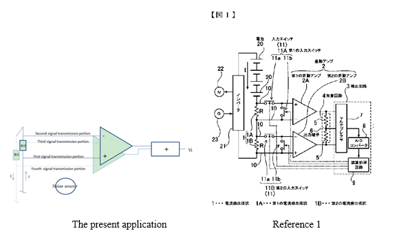
Fig. 1 of Reference 1 shows a current detection circuit that detects a charging current and a discharging current of a battery 20 charged by a generator 23 and subjected to regenerative braking or driven by a motor. The circuit includes, connected in series, a first current detection resistor 1A, a second current detection resistor 1B, a first difference amplifier 2A, a second difference amplifier 2B, an added circuit 4 and a detection circuit 3.
[Case Analysis]
It seems that claim 1 is distinguished from Reference 1 merely by the close arrangement of the transmission lines. Based on this superficial distinguishing technical feature, the technical problem can be easily determined as “facilitating the arrangement of the signal transmission portion”. However, this is a universal technical problem; most circuit layouts can be deemed aiming to facilitate the arrangement. Following this thought, the distinguishing technical feature may be determined to be easily conceivable. This is a common hindsight in the assessment of inventiveness.
However, a completely opposite conclusion can be made through a review of the process of forming the invention of the present application.
The inventor first recognized the detect that the stimulated differential signal changes when affected by external noises in its transmission channel, which causes decrease in the current detection accuracy.
In subsequent study, the inventor discovered the underlying cause of the technical problem of “affected by external noises”: a distance between the external noise source and the differential signal transmission portion leads to a corresponding degree of influence of the external noises remaining in the output signal of the differential signal transmission portion.
Thence, the inventor arranged the first transmission portion and the fourth transmission portion close to each other and arranged the second transmission portion and the third transmission portion close to each other, thereby solving the technical problem and obtaining the technical solution of the present application by which it is possible to detect a current at high accuracy, without being affected by external noises.
On the contrary, Reference 1 aims to detect a failure caused by failure of the current detection line while simplifying the circuit layout. It does not recognize the technical problem caused by the influence of an external noise source, not to mention the underlying cause for the technical problem relating to the difficulty in eliminating the influence of the external noise source i.e. “a distance between the external noise source and the differential signal transmission portion leads to a corresponding degree of influence of the external noises remaining in the output signal of the differential signal transmission portion”. By the distinguishing technical feature, the present application solves the above technical problem. Since the underlying cause of the influence of an external noise source cannot be easily found, the distinguishing technical feature is not obvious to those skilled in the art. In addition, those skilled in the art would have not expected the technical effect of eliminating the influence of the external noises remaining in the output signals so as to detect the current more accurately.
Following the above thoughts, I made a response to the office opinions on behalf of the applicant. The present application was granted a patent right subsequently.
[Conclusion]
In the assessment of inventiveness using the three step method, there is a tendency to neglect the deeper aspect of the technical problem, i.e., the cause of the technical problem. If the technical problem is simply determined as the inherent function or technical effect of the technical means employed by the applicant, the contribution made by the applicant by recognizing the cause for the technical problem may be left out. Therefore, we cannot simply determine that the technical means is obvious based on a technical problem determined without considering the inventive concept and the contribution made by the applicant by recognizing the cause for the technical problem.
2. Case 2: determining teachings for combination based on inventive concept
Claim 1 claims a PCVD method. Compared with Reference 1, the claim has the following distinguishing technical feature: supplying plasma-reactive gas in one pulse, and selecting the length and the position of the pulse to fall in a longitudinal position corresponding to the deposition oscillation, the deposition oscillation may be a variation in the thickness or composition of the deposited glass over the length of the substrate tube.
The present application aims to provide a substrate tube with a vapor-deposited glass layer of uniform thickness and refractive index alpha value in an axial direction.
Reference 1 discloses a device and method for PCVD on an inner coating layer of a glass tube. During the PCVD process, a main gas flow containing or nor containing a glass-forming gas and a basic amount of fluorine-containing compound. When the reaction zone is located near or at the reversal point of the hollow glass substrate tube, oxygen carrying an additional amount of fluorine-containing compound is added, to reduce the total amount of hydroxyl groups in the deposited glass and reduce the attenuation of an optical signal caused by Rayleigh scattering.
Reference 2 mentions varying the composition of the doped glass-forming gases supplied to the interior of a hollow glass substrate tube as a function of the position of the plasma zone during the deposition of glass layers, to control the thickness and the refractive index in the longitudinal direction of an optical preform.
[Case Analysis]
In Reference 1, oxygen carrying an additional amount of fluorine-containing compound in one pulse is added. Objectively speaking, oxygen is a plasma-reactive gas.
Reference 2 discloses determining the amount of the dopants by a function of the longitudinal direction of the reaction zone in the substrate tube and supplying the determined amount of the dopants through one or more gas flow to adjust the composition of the glass-forming gases, thereby solving the problem of non-uniform thickness and refractive index. Under the teaching of Reference 2, those skilled in the art can conceive the idea of selecting the strength and the position of the pulse for supplying the plasma-reactive gas during supplying the plasma-reactive gas in one pulse in Reference 1, so that the plasma-reactive gas falls in a longitudinal position corresponding to the deposition oscillation to guarantee the uniform thickness or refractive index in the axial direction of the glass tube.
However, reviewing the R&D process of the present application, it is found that Reference 2 cannot teach to combine the distinguishing technical feature with Reference 1.
Firstly, the inventor noticed that the thickness and the refractive index of glass substrates formed by PCVD vary at different positions, i.e., the problem of non-uniform thickness and refractive index.
Subsequently, through experiments observation and analysis, the inventor made it clear that this problem is caused because the plasma’s length and frontline position substantially vary relative to the position of the metal wall of the furnace. The continuously varying frontline position of the plasma leads to change of position of the deposition front relative to the position of the resonator. As a result, the thickness and the refractive index change in different positions.
Knowing this, the inventor had the idea of making improvements in terms of the plasma. The inventor applied a specific gas (reactive to the plasma) according to the axial direction of the plasma to offset the movement of the frontline of the plasma. Specifically, the plasma-reactive gas is supplied to a substrate tube where formation of glass happens so that the plasma-reactive gas reacts to the plasma to reduce the dimension of the plasma, thereby changing the position of the frontline of the plasma, minimizing the deposition oscillation. Thus, the technical solution of the present application was obtained.
On the contrary, although Reference 2 also mentions the technical problem of non-uniform thickness and refractive index of glass layers, it determines that the cause for the non-uniform thickness of the glass layer lies in the deposition of the glass layer in the substrate tube. Since an increased deposition speed will lead to deterioration in the uniformity of the glass layer, the amount of dopant needs to be accurately set to solve the problem of non-uniform refractive index.
Based on the different cause for the technical problem, Reference 2 employs a technical solution completely different from the present application. Reference 2 uses dopants such as GeCl
4 and C
2F
6 to increase or decrease the refractive index to control the refractive index of the optical preform in the longitudinal direction. In other words, Reference 2 achieves a substantively uniform refractive index distribution by adding dopants to vary the composition of the deposition glass and achieves the uniform thickness by precisely control of the flow rate of the gas flow. Different from Reference 2, the present application changes the plasma per se used for the deposition glass, using the plasma-reactive gas to react to the plasma so that the dimension of the plasma for the deposition glass reduces, thereby affecting the thickness or composition of the glass.
As shown above, Reference 2 does not at all recognize that the plasma itself causes the variation of thickness and refractive index according to the position as the present application does. Those skilled in the art can hardly conceive the idea of solving the technical problem of non-uniform thickness and refractive index by a solution of changing the plasma.
Following the above thoughts, I made a response to the office opinions on behalf of the applicant. The Examiner was convinced; and the present application was granted a patent right subsequently.
[Conclusion]
In determining the teaching for combination provided by an additional reference document, not only the universal technical problem as the first aspect but also the deeper aspect of the technical problem should be considered based on the inventive concept. If the reason A for the technical problem noted by the present application is completely different from the reason B for the technical problem noted by the reference document, and the reference document does not recognize the reason A, those skilled in the art can hardly be taught by the reference document to arrive at the technical means coping with the reason A.
III. Suggestion
Based on the analysis of the above two cases, to objectively assess the inventiveness of a patent application without being blinded by hindsight, we should focus more on the reason behind the technical problem than the technical problem per se. In other words, we need to stick to the inventive concept and review the key links of the invention.
Firstly, the inventive concept can be reviewed following the chain of technical problem—cause for the problem—technical means coping with the cause for the problem.
Subsequently, we can analyze the reference document to check whether the reference document also follows the above chain.
Accordingly, it can be determined whether the reference document teaches the improvement or a combination of technology.
In this manner, it will be easier to convince the Examiner from the technical perspective when we make a response to the office opinions, helping the Examiner to have objective and fair understanding of the application while increasing the possibility of obtaining a reasonable scope of protection.
It should be noted that, in the substantive examination and the reexamination procedures, the disclosure contained in the application document weighs in the consideration of the examiner and the collegial panel with regard to the arguments in the observations. To enable the analysis of the cause for the technical problem to be solidly grounded, it is recommended that the process of discovering and solving the technical problem be detailed in drafting the application document, so as to provide basis for making a response to the office opinions during the prosecution.
Furthermore, in case the technical disclosure provided by the inventor omits the description of the three aspects of the technical problem, patent attorneys may follow the above chain of thoughts to explore deeper into the technology in the communication with the inventor to better draft the application document, so as to form valuable patent application documents fully exhibiting the inventive contribution made by the inventor.
